Four placement concepts
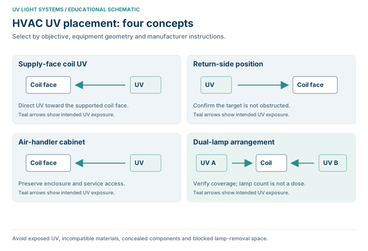
| Example | Potential objective | What to verify |
|---|---|---|
| Supply-side coil face | Irradiate the leaving-air face of the coil | Coverage, temperature, pan and material exposure |
| Return-side location | Treat a reachable coil face or a separately designed airstream zone | The lamp may not see the coil through intervening parts |
| Inside an air handler | Target a specific cabinet surface or coil | Enclosure, insulation, wiring and service access |
| Dual lamps | Reach supported areas a single lamp leaves untreated | Overlap, shadows, electrical load and replacement clearance |
Trace both airflow and radiation
Air direction alone does not establish the radiation path. A filter, blower housing or coil assembly between a lamp and a target can block exposure. Ask the installer to show the actual target on your equipment rather than pointing to an open section of duct.
For moving-air treatment, the exposure zone must suit the airflow and tested configuration. Simply placing a surface lamp in a return duct does not create a validated disinfection system.
Use how HVAC UV works and the surface versus airstream comparison to distinguish these paths.
Locations to avoid
- An exposed location where occupants or service personnel can receive UV.
- A position that irradiates unprotected incompatible wiring, plastics or filter media.
- A mount that risks striking concealed coils, lines or other equipment.
- A location that prevents lamp removal or blocks an original service panel.
- An unsupported temperature or moisture environment.
There is no safe universal cutting depth or hole location. Model-specific manuals and an equipment assessment determine those details.
Electrical and service-clearance planning
Confirm the supply requirements, controller location and whether new electrical work is necessary. An available low-voltage transformer is not automatically suitable. Leave the prescribed space for removing the lamp and maintaining both the UV and original HVAC equipment.
Use qualified help where electrical connections, enclosure modification or radiation assessment is involved. Do not energize an unshielded lamp to test the arrangement or bypass an interlock to show that it lights.
Document the chosen configuration
Keep the model, installed location, target, shields, service interval and any commissioning checks in the handover record. Ask why that arrangement suits the equipment and how maintenance will preserve it.
The installation guide covers the full scope. For the target itself, read evaporator-coil treatment and air-handler compatibility.
Choosing a UV System: What Actually Matters
After resolving this page’s technical question, compare the following requirements for your installation. The HVAC buying guide brings the full specification record together.
| Criterion | What to verify |
|---|---|
| Coverage and performance evidence | Compare coil dimensions and cabinet geometry; for moving air, require evidence at the intended airflow and exposure conditions. |
| Wattage and electrical supply | Check complete-system input, required voltage, ballast/controller and the proposed power source with the installer. |
| Materials and ozone characteristics | Review shielding, component compatibility and model-specific ozone/emissions documentation. |
| Replacement lamps and service | Obtain the exact lamp part number, rated replacement interval, current price, availability and removal clearance. |
Questions People Ask Next
Is supply-side placement always best?
No. It can be suitable for a particular coil face, but the correct configuration depends on the equipment and objective. A supply-side label does not establish coverage, safe materials or an adequate airstream dose.
Can a lamp go before the filter?
Only if a supported design permits that location and protects the filter and other materials. A lamp upstream of components may not reach the intended coil at all. Follow the manufacturer’s placement requirements rather than treating position alone as proof of effectiveness.
Are two lamps better than one?
They can help reach different areas in a supported arrangement, but count alone is not a performance measure. Extra lamps add service and compatibility considerations. Ask what additional surface or exposure each lamp provides.
How many inches from the coil should a lamp be?
Use the specified range for the actual UV equipment and installation. A generic distance cannot account for lamp design, coil geometry or nearby materials. The illustration intentionally omits mounting dimensions because it is not an installation template.
Can I use the viewing opening to inspect the lamp?
Use only the manufacturer’s supported indication or viewing method, if one is provided. Do not create an opening, remove a shield or look directly at an energized germicidal lamp. Visible glow does not verify treatment dose.
Sources & further reading
Primary references for the principles discussed. Manufacturer instructions take precedence for a specific system; no independent technical reviewer is claimed.